1. 產品結束view
The EPEVER Tracer BN Series MPPT Solar Charge Controller is an advanced, efficient, and multi-functional device designed for off-grid solar systems. It utilizes Maximum Power Point Tracking (MPPT) technology to maximize energy harvest from solar panels, ensuring optimal charging for your battery bank. This controller is suitable for various applications, including telecommunication base stations, household systems, street lighting, and wilderness monitoring systems.
主要特點包括:
- Advanced MPPT technology with tracking efficiency no less than 99.5% and maximum conversion efficiency of 98%.
- Reliable automatic limit function of maximum PV input power, preventing overload under any circumstances.
- 寬 MPP 工作卷tage 範圍。
- 採用壓鑄鋁設計,散熱性能優異。
- 12/24VDC自動系統音量tage 識別。
- Multiple load control modes: manual control, light ON/OFF, light ON+Timer, and time control.
- Supports 4 charging options: Sealed, Gel, Flooded, and User-defined.
- PC monitoring and external display unit (like MT50) connectivity for real-time data checking and parameter setting, with software upgrade support.
- Modbus communication protocol interface for expanded applications and monitoring.
三、產品組成
Familiarize yourself with the main components and interfaces of the Tracer BN series solar charge controller:

Figure 2.1: Controller Components Overview
This image displays the EPEVER Tracer BN Series Solar Charge Controller with key components labeled, including the Heat Sink, Button, Charging LED indicator, Battery LED indicator, RTS port, RS485 Port, Solar Terminal, Battery Terminal, and Load Terminal.
- 散熱器: Dissipates heat generated during operation to maintain optimal performance.
- 按鈕: Used for manual control of the load and navigating settings.
- 充電 LED 指示燈: Shows the status of PV (solar panel) charging.
- 電池 LED 指示燈: Displays the battery charging status.
- RTS (Remote Temperature Sensor) Port: Connects an optional remote temperature sensor for accurate battery temperature compensation.
- RS485連接埠: Communication interface for connecting to PC, MT50 remote meter, WiFi, or Bluetooth modules.
- Solar Terminal (PV): 連接到太陽能電池板陣列。
- Battery Terminal (BATT): 連接到電池組。
- 負載端子: 連接直流負載。
3. 設定與安裝
正確的安裝對於太陽能充電控制器的安全高效運作至關重要。請仔細按照以下步驟操作:
3.1 開箱和初步檢查
影片 3.1:開箱及組件概覽view
This video demonstrates the unboxing process of the EPEVER Tracer BN MPPT Solar Charge Controller and provides a visual overview of its main components and ports, including the PV charging LED indicator, battery charging LED indicator, button, PV terminals, battery terminals, load terminals, heat sink, RTS port, and RS485 port.
- Carefully open the packaging and remove the controller and any accessories.
- Inspect the controller for any visible damage. If damage is found, contact your supplier.
- 請確保所有列出的組件都已到位。
3.2 接線連接
重要安全注意事項: While wiring the controller, ensure that the circuit breaker or fuse is 不是 closed. Verify that the positive ("+") and negative ("-") leads are connected correctly to prevent damage to the controller or other components.
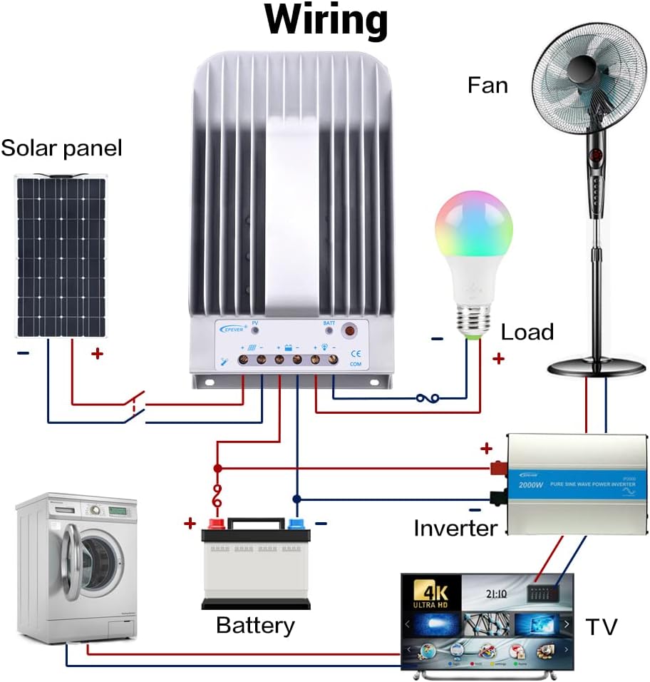
圖 3.2:典型系統接線圖
This diagram illustrates a typical solar power system setup, showing the connection of the solar panel to the controller, the controller to the battery, and the controller to various DC and AC loads via an inverter. Ensure correct polarity for all connections.
The connection order is critical:
- 連接電池: First, connect the battery to the controller's battery terminals. Ensure correct polarity (positive to positive, negative to negative). The controller will automatically detect the system voltage (12V/24V). The controller supports Lead-acid Batteries (Sealed, AGM, Gel, Flooded) and User-defined settings.
- 連接負載: Next, connect your DC loads to the controller's load terminals.
- Connect the Solar Panel (PV): Finally, connect the solar panel array to the controller's PV terminals.
The disconnection order is the reverse: PV -> Load -> Battery.
Refer to the following table for recommended wire sizes based on controller model:
| 模型 | Wire Size (AWG/mm²) |
|---|---|
| 示踪劑1215BN | 12AWG(4mm²) |
| 示踪劑2215BN | 8AWG(10mm²) |
| 示踪劑3215BN | 6AWG(16mm²) |
| 示踪劑4215BN | 4AWG(25mm²) |
4. 操作說明
Once the controller is correctly wired and powered, it will begin operating automatically. The LED indicators provide visual feedback on the system status.
4.1 負載控制
The controller offers various load control modes. In manual control mode, you can toggle the load on or off using the controller's button.
Video 4.1: Load Manual Mode Operation
This video segment demonstrates how to manually turn the load ON/OFF by pressing the 'ENTER' button on the controller when it is in load manual mode.
Other load control modes (Light ON/OFF, Light ON+Timer, Time Control) can be configured using an external display unit (like MT50) or PC/APP software connected via the RS485 port.
4.2 Monitoring and Parameter Setting
The controller supports various accessories for enhanced monitoring and parameter adjustment:

Figure 4.2: Controller with Communication Accessories
This image illustrates how the solar charge controller can be connected to various communication accessories such as the MT50 remote meter, eBox-WIFI-01 for WiFi monitoring, eBox-BLE-01 for Bluetooth monitoring, and a PC via a USB to RS485 cable for detailed system management.
Optional accessories for monitoring and control:
| 配件 | 描述 |
|---|---|
| Remote Temperature Sensor (RTS300R47K3.81A) | Acquisition of battery temperature for temperature compensation of control parameters. The standard length of the cable is 3m (can be customized). The RTS300R47K3.81A connects to the port (4th) on the controller. 筆記: If the temperature sensor is short-circuited or damaged, the controller will be charging or discharging at the default temperature 25 °C. |
| USB to RS485 cable (CC-USB-RS485-150U) | USB to RS-485 converter used to monitor each controller on the network using Solar Station PC software. The length of cable is 1.5m. The CC-USB-RS485-150U connects to the RS-485 Port on the controller. |
| OTG cable (OTG-12CM) | Used to connect a mobile communication cable and able to achieve real-time monitoring of the controller and modification of the parameters by using mobile APP software. |
| Remote Meter (MT50) | MT50 can display various operating data and fault of the system. The information can be displayed on a backlit LCD screen, the buttons are easy-to-operate, and the numeric display is readable. |
| WiFi Serial Adapter (eBox-WIFI-01) | After the controller is connected with the eBox-WIFI-01 through the standard Ethernet cable (parallel cable), the operating status and related parameters of the controller can be monitored by the mobile APP software through WiFi signals. |
| RS485 to Bluetooth Adapter (eBox-BLE-01) | After the controller is connected with the eBox-BLE-01 through the standard Ethernet cable (parallel cable), the operating status and related parameters of the controller can be monitored by the mobile APP software through Bluetooth signals. |
| Logger (eLOG01) | 控制器透過RS01通訊線與eLOG-485連接後,可記錄控制器的運作資料或透過上位機軟體監控控制器的即時運作狀態。 |
筆記: For setting and operation of accessories, please refer to their specific instructions.
5、維護保養
定期維護可確保太陽能充電控制器的使用壽命和最佳性能:
- 清潔度: Keep the controller clean and free from dust and debris. Use a dry cloth to wipe the exterior.
- 連接: 定期檢查所有線路連接是否緊固。連接鬆動會導致過熱和損壞。
- 通風: Ensure the heat sink fins are not obstructed to allow for proper airflow and heat dissipation.
- 環境: Operate the controller within its specified ambient temperature and humidity ranges.
6。 故障排除
If you encounter issues with your EPEVER solar charge controller, consider the following basic troubleshooting steps:
- 無電源/顯示: 檢查電池連接並確保電池電壓正常tage is within the controller's operating range. Verify fuses or circuit breakers are not tripped.
- 不充電: 確保太陽能電池板連接正確且接收充足的陽光。檢查光電輸入電壓。tage and current. Verify PV circuit breaker/fuse.
- 加載失敗: Check load connections and ensure the load is not exceeding the controller's rated current. Verify the load control mode settings.
- Abnormal LED Indicators: Refer to the full user manual for specific error codes or indicator patterns to diagnose issues.
For complex issues or persistent problems, contact technical support.
三、技術規格
The following table provides detailed technical specifications for the Tracer BN series, including the 40A model (Tracer4215BN):
Video 7.1: Technical Specifications Overview
This video segment displays a table detailing the technical specifications for the Tracer BN series MPPT Solar Charge Controllers, including electrical and environmental parameters for various models (Tracer1215BN, Tracer2215BN, Tracer3215BN, Tracer4215BN).
| 物品 | Tracer 1215BN | Tracer 2215BN | Tracer 3215BN | Tracer 4215BN |
|---|---|---|---|---|
| 標稱系統容積tage | 12 / 24VDC自動 | |||
| 額定充電電流 | 10A | 20A | 30A | 40A |
| 額定放電電流 | 10A | 20A | 20A | 20A |
| 電池容量tag範圍 | 8V~32V | |||
| 最大限度。 光伏開路電壓tage | 150V(最低工作環境溫度) 138V(環境溫度25℃時) | |||
| MPP體積tag範圍 | 電池容量tage+2V ~ 108V | |||
| 最大限度。光電輸入功率 | 130W(12V) 260W(24V) | 260W(12V) 520W(24V) | 390W(12V) 780W(24V) | 520W(12V) 1040W(24V) |
| 自用 | ≤60mA(12V); ≤30mA(24V) | |||
| 放電迴路電壓tag滴滴 | ≤0.15V | |||
| 溫度補償係數 | -3mV/°C/2V(預設) | |||
| 溝通 | RS485(RJ45介面) | |||
| 接地 | 常見的負面 | |||
| Ambient temperature range* | -35℃~+55℃ | |||
| 儲存溫度範圍 | -35℃~+80℃ | |||
| 濕度範圍 | ≤95% (NC) | |||
| 外殼 | IP30 | |||
*Please operate controller at permitted ambient temperature. If over permissible range, please derate capacity accordingly.
8. 保固和支持
EPEVER products are designed for reliability and performance. For warranty information, please refer to the documentation included with your purchase or visit the official EPEVER website. If you require technical assistance or have questions regarding your Tracer BN series solar charge controller, please contact EPEVER customer support or your authorized dealer.